
Lotus Convention Centre Solution Guide
Welcome to the solution guide for the Lotus Convention Centre.
Before we start, I encourage you to try and create this model on your own if you haven't yet. It's not essential but it will help you learn Grasshopper better. Not to mention, if you get stuck, you can always reference this solution guide to help you out. The questions and thoughts that you get from trying it yourself can also help frame your mind as you go through this guide.
When you're ready, let's get started.
Model Anatomy
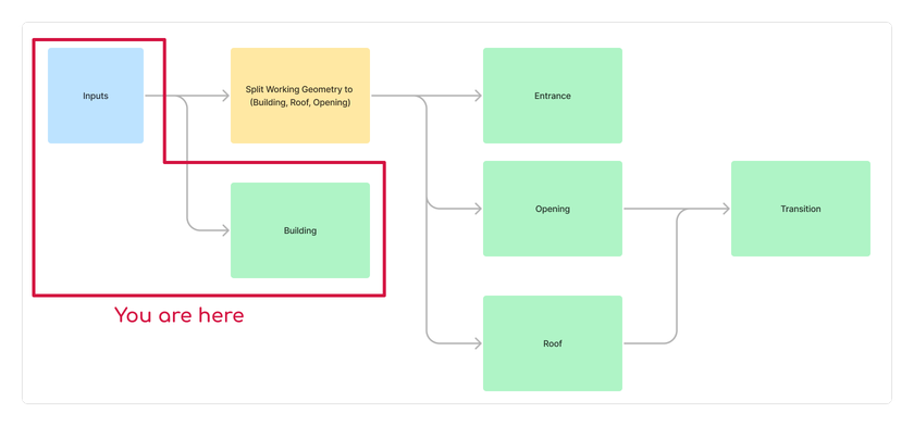
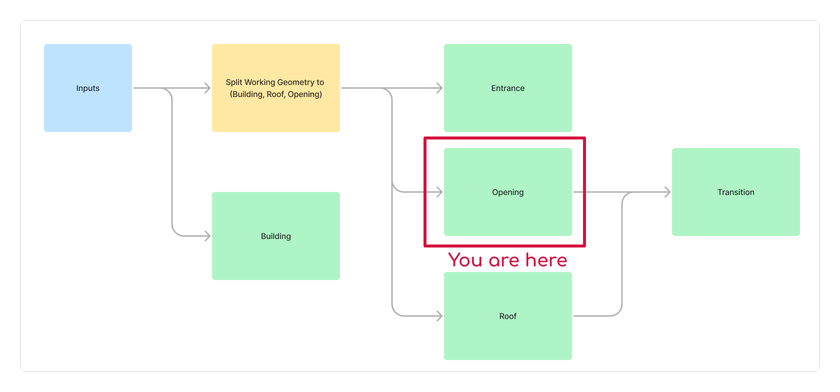
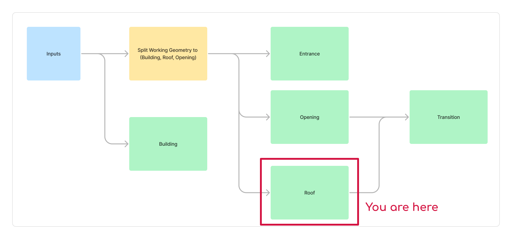
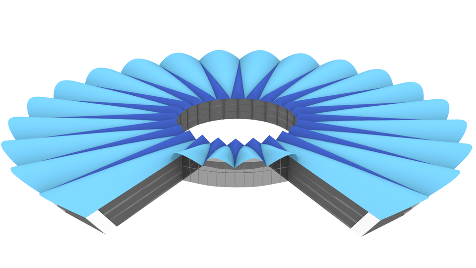
Just as a reminder, here is the breakdown of the model.
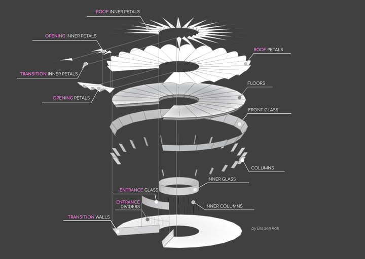
This model is pretty detailed and has a lot of parts to it. So, naturally, the grasshopper script would be detailed too. To help you navigate the script, I have created a "mini-map".
![[Lotus-script-mini-map-3.png]] Use this mini-map to guide you on where to place or look for things in the Grasshopper script.
Modelling Steps
From a high-level view, this is how the model is created in Grasshopper.
- Using some dimensions, create two circles and divide them into a number of segments
- Based on another set of inputs, split the segmented curve into the opening and roof.
- Use the curves to create the elements of the building (walls, columns, floors, etc)
- Use the opening geometry to create the entrance
- Then use the same geometry to create the inner petals and petals for the opening
- Go "back" in the script and create the inner petals and petals for the roof
- Then use the petals from the opening and roof to make the transition inner petals
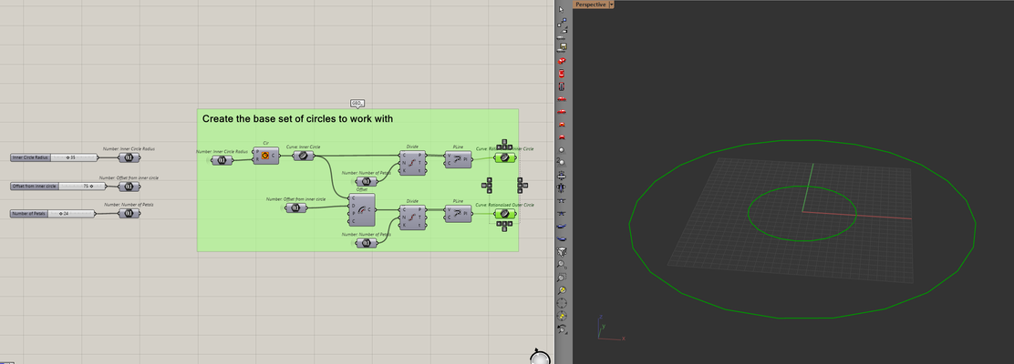
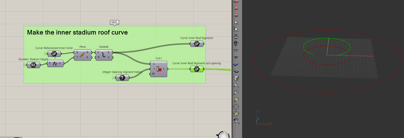
Creating the working geometry (starting curves)
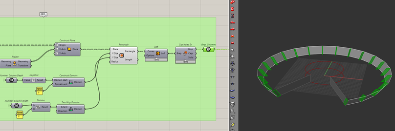
To start building this model, I will set out a few circles. Here, we need three inputs, the radius of the inner circle, the offset from the inner circle and how many petals are on the model. Using these inputs, I will create a circle and subdivide it by the number of petals.
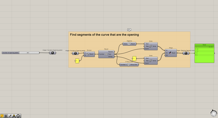
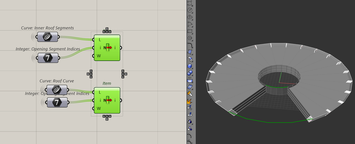
To then split the curve for the opening, I can let the user control how many segments belong to the opening. Using that number, I can create a list of indices to filter/extractlets the segments. I will create the list in a way that let's me extract segments from the top and the bottom of the list.
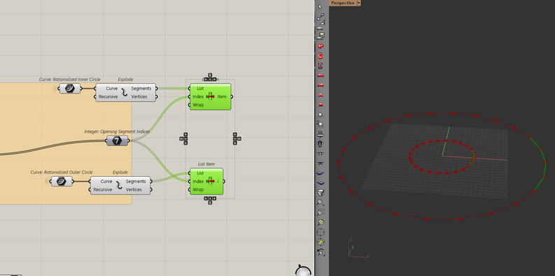
Once I have the list, I can either use the list item component to select the opening segments or I can use the cull item component to exclude them.
As the user selects the number of segments for the opening, it will always be where the circles start and end. This point is known as the seam of the curve. By default, Grasshopper will put this seam at a point in the furthest x-direction. But I prefer the opening to face me (the negative y-direction). To change that, I can adjust the seam to face the negative y-direction using the align curve seams component.
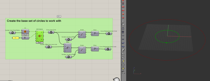
So, now any segments that the user chooses will always be in the negative y-direction.
Next, I will use the circles and indices to create curves for the roof. Which for the inner circle, is just a matter of moving it upwards by some distance.
It's more complicated for the outer circle, I need to move and scale the curve by a factor. This is to introduce a slant when we make the rest of the elements later.
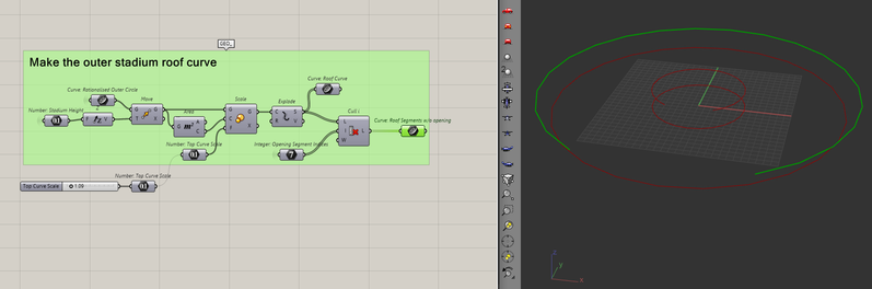
Once I have all the curves, it's time to move on to creating the building elements.
Create the Building
There are a few building elements in this model and each part is relatively simple to create. I will start with the transition walls.
The Transition Walls
I will use the endpoints of the outer circle and roof curve to create the walls. It's a simple matter of creating a line between the two curves and then lofting them. Let me just bring all the curves in one spot.
Then, I will make the lines and loft between them.
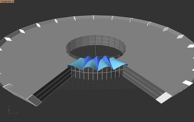
The Front Glass
Again, a pretty straightforward exercise. it's just a loft between all the segments of the outer roof and circle curves.
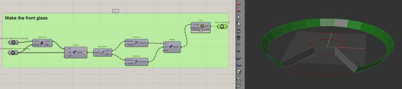
If it was hard to see the slant of the building with just the curves before, these panels should give you a good indication. Adjust that scale factor from before based on how slanted you want the model to feel.
The Columns
By using the lines from making the front glass, I will make the columns. It's about creating rectangles at the top and bottom of those lines, then lofting them.
To create those rectangles, I need planes that are facing the right direction. To do that, I need a vector from the origin to the bottom of each line. That vector will be the x-axis of the new plane.
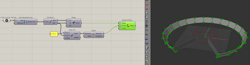
Then after setting some dimensions for the column sizes, I can create the rectangles and loft them.
The Floors
To create the floors, I want to loft between the outer and inner top/bottom curves. Because we have multiple floors throughout the building, I need a way to create multiple segments between the ground and the roof. I can do this by using the tween curve component.
After setting the number of floors I want in the model, I can plug that into the tween curve component to create curves between the roof and the ground.
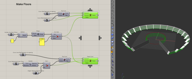
All that's left to do, is to add some thickness to the curves by extruding them upwards and then lofting between the outer and inner segments.
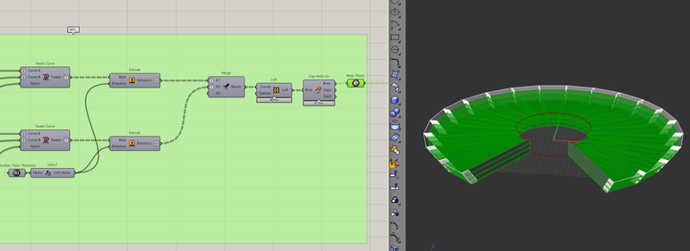
The Inner Columns
To create the inner columns, I'll just take the vertices of the inner roof and ground curve, create a circle then extrude them upwards by the building height.
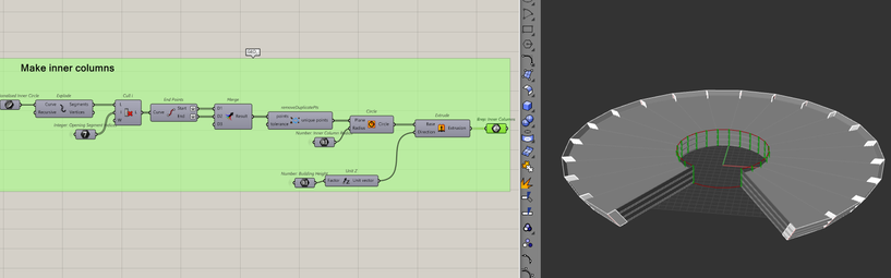
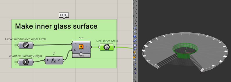
The Inner Glass Surface
The inner glass surface can be made by lofting the inner roof and ground curve (including the opening segments).
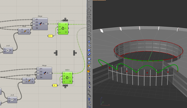
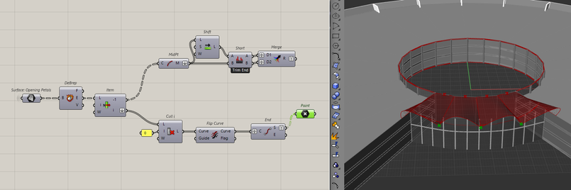
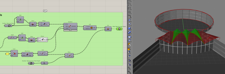
Making working geometry for the Opening
![[Lotus-Script-map-working-here.png]] Before I start making the entrance or the opening, I need to get its base geometry. The opening is "shorter" than the rest of the building and I need the curves that represent that. I'll start by pulling together the segments that make the opening from before.
To make the opening, I need to bring in those outer segments by a distance. To do that, I can scale that outer curve down by a factor.
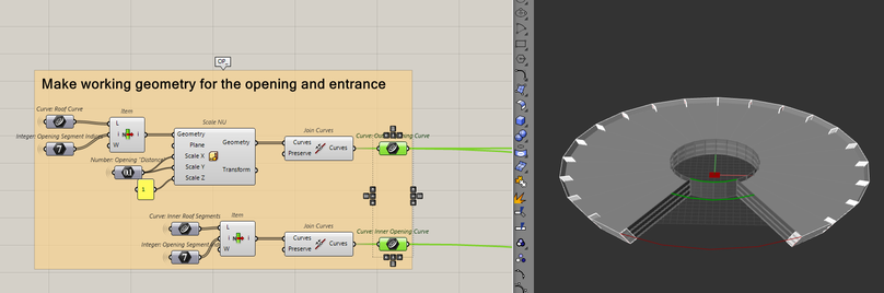
With the working geometry for the opening set, I'll start making the entrance
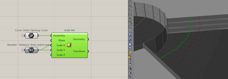
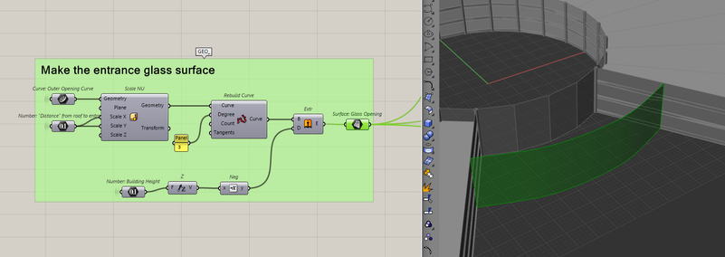
Making the Entrance
![[Lotus-script-map-entrance-here.png]] To add some realism to the model, the entrance of any building typically sits inwards from the roof. Noticed how when you exit/enter buildings, there is always some cover before the door. Like when it's raining and people huddle under it? That's why I am going to move the curve inwards by another factor to account for this.
To make the glass surface, it should just be an extrusion of the top curve downwards. But to add the dividers later on, I need to first rebuild the curve. I do this to get rid of the kinks and turn the polyline into a curve. That way when I extrude, I get a surface and not a poly-surface.
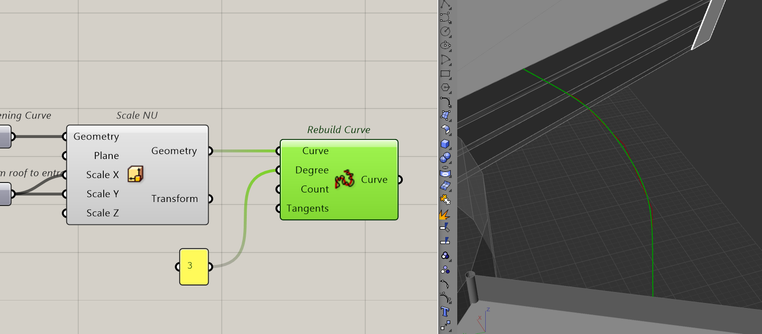
I'll explain why I do this later but for now, I will just extrude the curve downwards to create the glass surface.
Glass Dividers
In real life, you will now have a piece of glass that big. It would normally be made of several windows/doors. To account for this, I add "frames" to the surface by using it's isocurves. Isocurves are the curves that define a surface.
To get a surface's isocurves, we need to specify where on the surface to get the curves. Similar to how we place points with x and y, we can get a point on a surface with U and V.
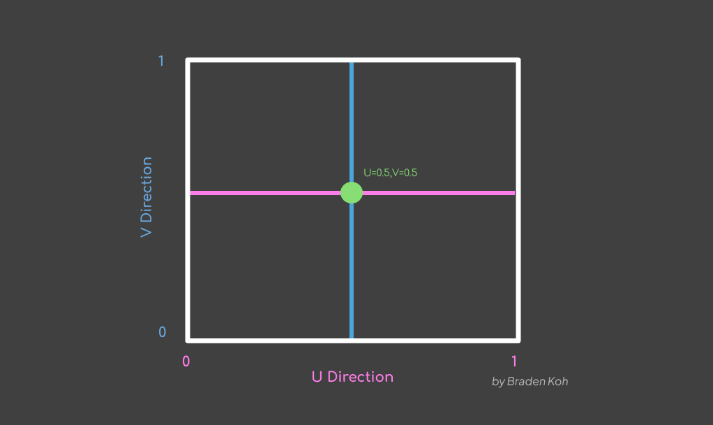
That means to get a list of isocurves in Grasshopper, I can create a list of UV "points" to extract curves from the surface.
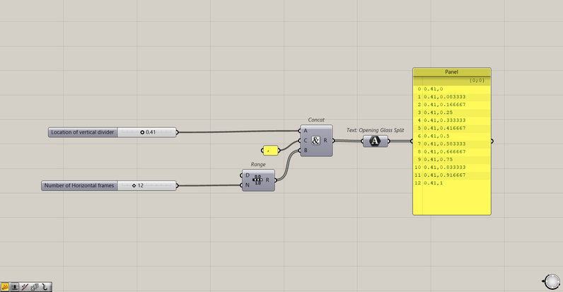
Here, I am specifying one U value and multiple V values because I only want one horizontal divider. You can always specify multiple horizontal and vertical dividers if you want more. I will then plug this list into the surface isocurves component to extract the curves.
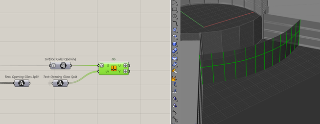
By rebuilding the curve before, I am working with one surface. Which means I can easily control how many isocurves to extract. If I didn't rebuild and had a poly-surface, I would have to manage the isocurves of multiple surfaces which I think is too much effort for this part of the model.
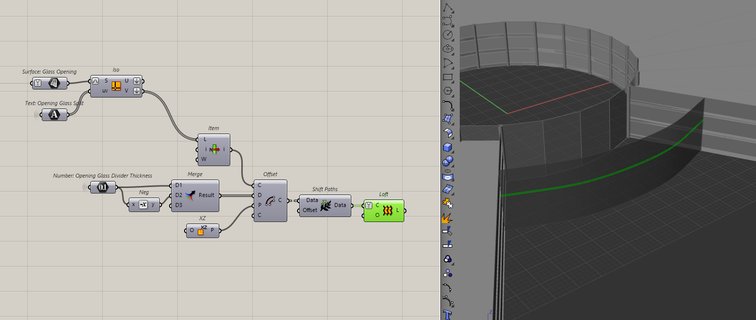
Now, these are just lines. If I want to make them into "frames", I need to add some thicknesses to them. I can do that by offsetting the lines by a number, and then lofting them. Let's start with the horizontal frame first because it's a simple offset in the vertical direction.
To offset the vertical frames, I have to use the plane of the surface to get the right direction for the offset. I can get that by using the evaluate surface component with the list of UV points I made before.
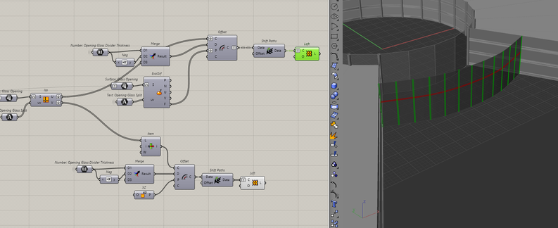
And with that we all the elements of our building modelled.
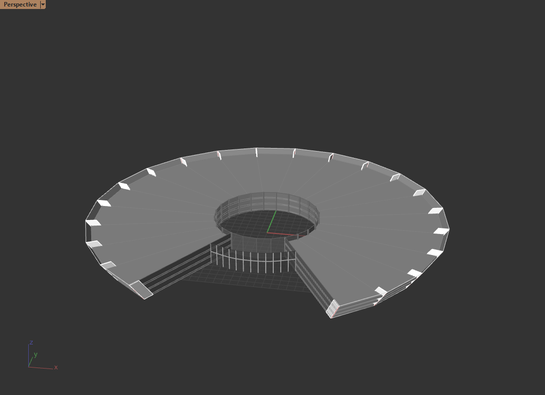
Making the opening
The opening and the roof both consist of two parts, the petals and the inner petals.
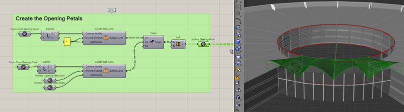
Making the petals
To make the petals, I will use the segments of the inner and outer roof curves. For each segment pair, I will make arches and loft them to make the petals. Each segment will be rebuilt with three points and I can move the middle point to control the arch. It's starting to get abstract, so let's look at how this is done in Grasshopper.
If I take a line, divide it into three points, then move the middle point upwards and/or forwards, then interpolate the points, I can turn the line into a curve.
By applying this logic to each segment, I can create the arches in the roof.
To create that "flat to arch" look, I will keep the inner segments flat. But even though they are flat, I am still rebuilding the segment, because I want the two segments to have a similar definition when I loft them. This just makes for a cleaner surface.
Since this logic of building the petals will be the same for the roof and the opening. I will turn this workflow into a cluster. I do this to have a single source of truth for this workflow, now if I make any changes to this workflow, it will change everywhere this cluster is used.
Now, all that's left is to loft the two curves together.
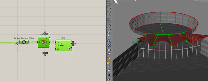
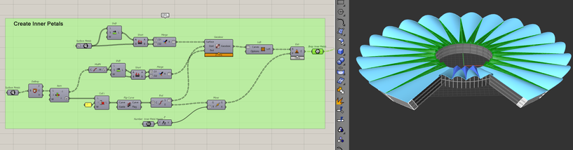
Making the inner petals
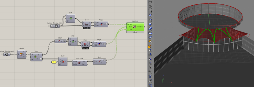
To create the inner petals is slightly more complicated because we need to create geodesic curves. A geodesic curve is the shortest path between two points on a surface.
For a geodesic to work, I need a surface, a start point and an end point. I can get all these from the petal surfaces. Let's start by extracting our inputs from them.
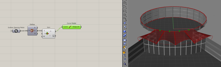
Since I made the petals by lofting from the inner to the outer segment, the order of the edges will always be the same. This lets me safely use the list item component as the edges always appear in a consistent manner.
Now, I want the midpoint of the shortest edge of the surfaces. These will be the start points of the geodesic curves.
To create the inner petals, I need two geodesic curves, one for each side of a petal. That means I need the midpoints relative to each other in a tree.
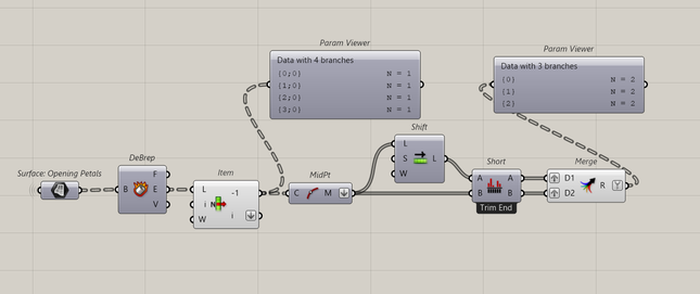
Each branch of the tree is an inner petal that will have two midpoints. I need to do the same data manipulation with the petals so that I have two surfaces for each midpoint to travel.
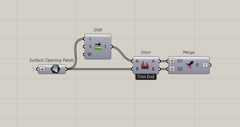
All I need now is the end point of the geodesic. I can get that by using the start point of the long edge of the petal surface.
This time, I don't need to duplicate its data because each inner petal has the same endpoint. Now, I can plug all of that into the geodesic curve component to get the curves.
Then, lofting the two curves will create the base for the inner petals.
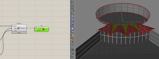
I can then move the end point upwards by some distance. This will be the height of the inner petal. Finally, I'll extrude the base to that point, creating the inner petal.
With that, we have the opening of the building modelled.
Making the Roof
To create the roof, I can take advantage of the workflows from making the opening as they are largely similar.
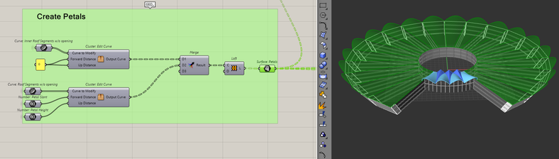
Making the petals
I will use the clusters that we made before to make the rest of the petals.I will just have to use the roof curves instead of the opening curves.
Making the inner petals
And again, similar to the opening inner petals, I will create the inner petals for the rest of the roof.
Making the transition inner petals
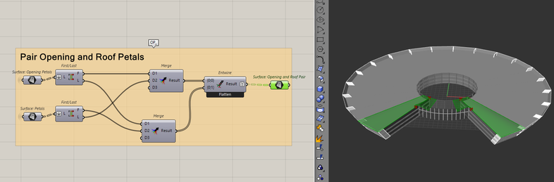
With all the petals and inner petals created for both the roof and the opening, I can create the final piece of the model, the transition inner petal.
First, I need to bring the petal surfaces from the opening and the roof in one spot. Specifically, the first and last surface of each.
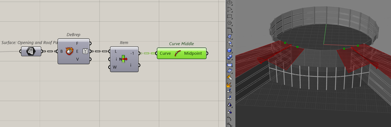
Similar to before, I need to get the inputs to make the geodesic curves. To get the start point, it's going to be the midpoint of the last edge of the petal surfaces.
To get the end points, I need first to get the relevant brep edges. In this case, it's the edges of the opening petals that are the second furthest in the x-direction. It's the second furthest because the arch of the opening petal will always be the furthest in the x-direction.
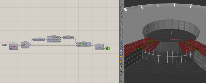
The endpoints of these edges will be the endpoints for the geodesic curve. And with all the data prepared, I can run the geodesic component.
Like before, I just have to loft and extrude upwards to create the inner petal.
Final Thoughts
And with that, we've finished modelling the Lotus Convention Centre. I will preview on all the geometry now and assign some colour to the different components.
This model pushed me to better manage my data because it had a range of different parts. It had parts that are independent of each other, like how the building doesn't affect the creation of the roof, but it also had dependent parts like how the logic to create the petals is the same for the roof and the opening.
It really challenged me to think about the best way to communicate and organise the model into a coherent script. The intricacies of the model also made me understand just how important it is to have clean data.
I really hope you enjoyed creating this model and learned something from it.
You can find the link to the script here: Lotus Convention Centre.gh