
Spiral Observatory Tower
Welcome to the Spiral Observatory Tower solution guide. The main feature of this model is its signature spiral shape and how all of its elements give it a "twisted" look. The main driver of this model is going to be the helix.
Before we start, I still encourage you to try creating this model if you haven't. Going through it on your own provides a good experience in using Grasshopper. With that in mind, I am also assuming that you know the basics of Grasshopper, so I won't be explaining what each component does. But I will explain my component and workflow choice throughout the model.
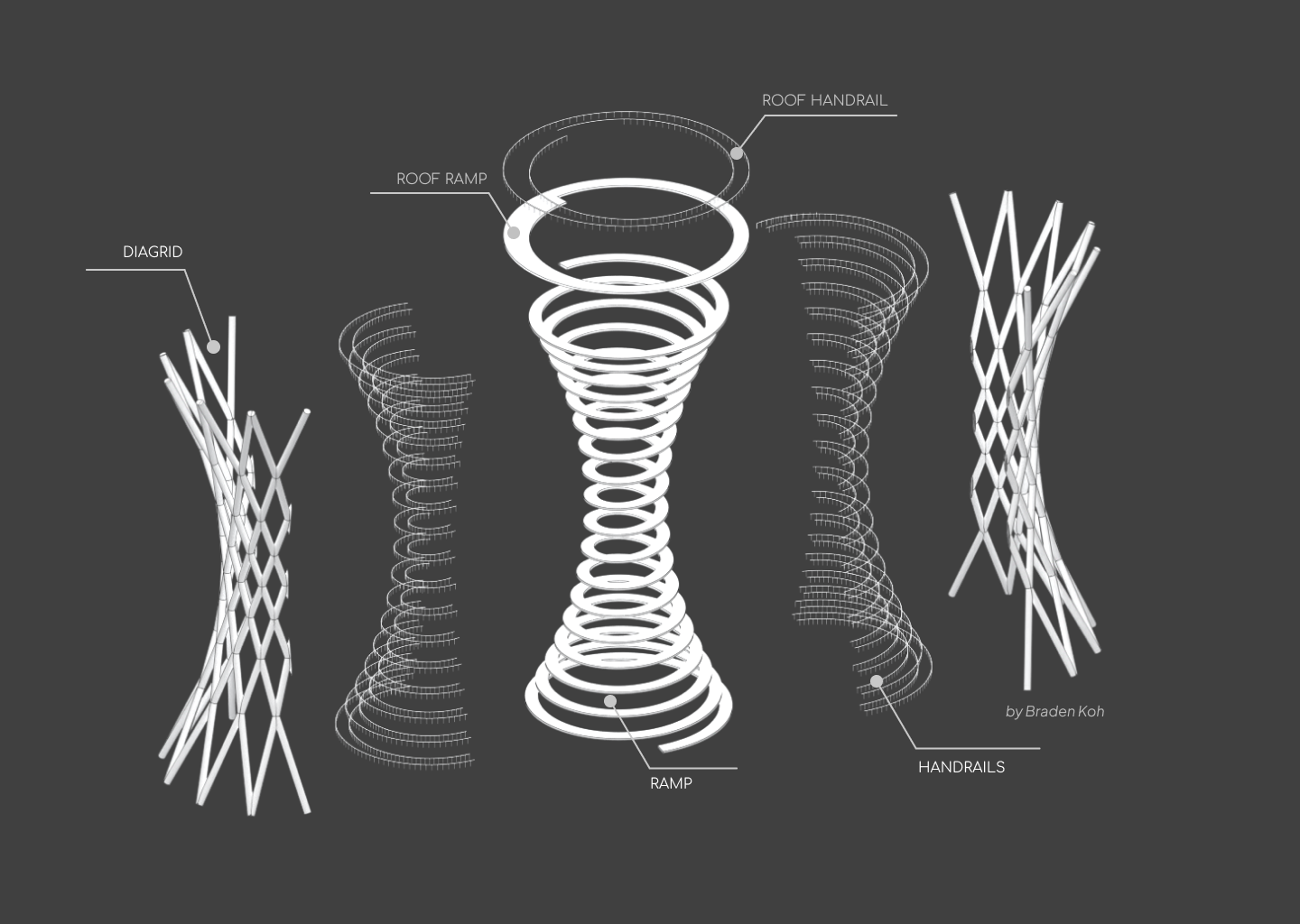
Tower Anatomy
As a reminder, this is the anatomy of the tower.
Modelling Steps
These are the high-level steps that I take to create this model.
- Defining the Helix
- Merging the Helix with the roof platform
- Modelling the ramp
- Modelling the roof ramp
- Modelling the handrails
- Modelling the Diagrid
Note: my way is not the only way to create this model, so it's perfectly fine if you have a different workflow.
Defining the Helix
The first step is to define the spiral feature of the tower. It's done by creating a helix using the tower's dimensions.
Because this is an abstract process, here's a visual of what I'll be implementing in Grasshopper.
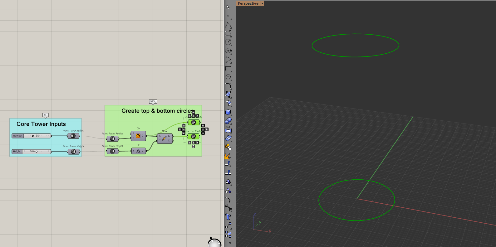
Create the Conical Surface
Let's define some basic input parameters for the tower like its height, radius, etc. Using these dimensions, I'll then create two circles, one at the top and one at the bottom.
Then, I'll create a smaller circle in the middle by moving and scaling one of the two circles from before. Lofting through these circles will give a conical surface.
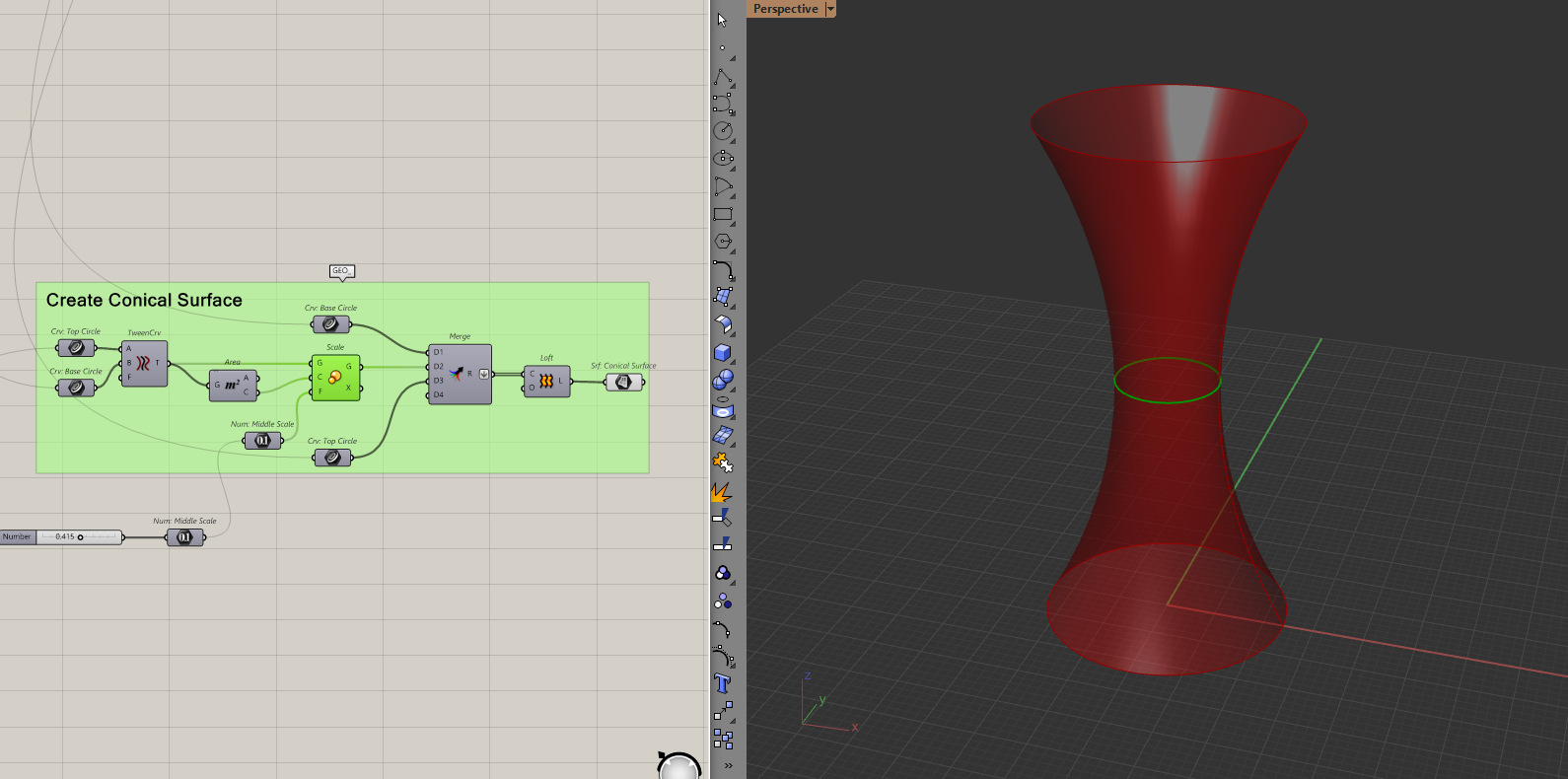
Because I used the scale component for the middle circle, it will resize if I change the radius of my tower. You can of course just create the smaller circle using another radius.
Create and linearly move a circle of points.
With the conical surface done, we now need to create a circle of points and move them upwards.
To do this, I will create some points based on the polar coordinate system. If this is new to you, polar coordinates are another way to place points. Similar to how we normally define points with x and y. We define a point in polar coordinates with a distance and an angle.
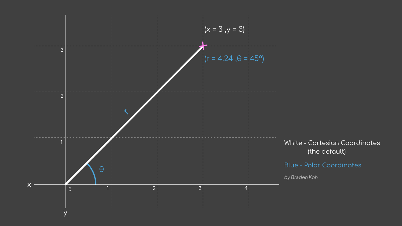
The reason I use this system is that it's much easier to define a circle in polar coordinates than in regular coordinates. All I need to do is give a distance (which is the tower radius) and an angle (0 to 2π).
I need more than one circle because I want to move these points upwards. This is known as a "turn" in the helix. The more circles I make now, the more "turns" the helix will have. It can be hard to visualise this but it will be obvious once I move the points later.
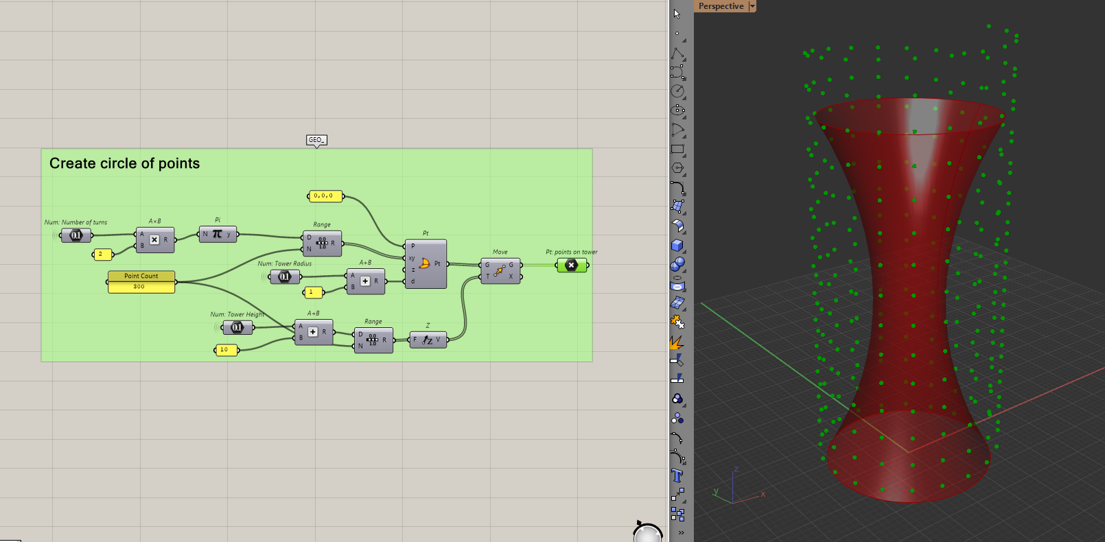
To do this in Grasshopper, let's use the polar coordinate component and make the circle of points.
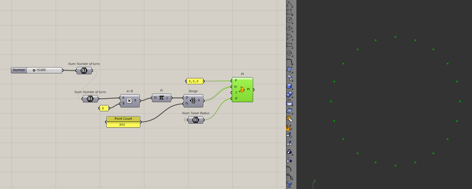
I am going to choose 15 turns and also I want 300 points across those 15 turns. There is no real reason behind the numbers, I just chose what looked good for the tower.
I'll then move those points upwards.
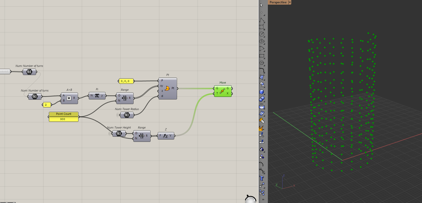
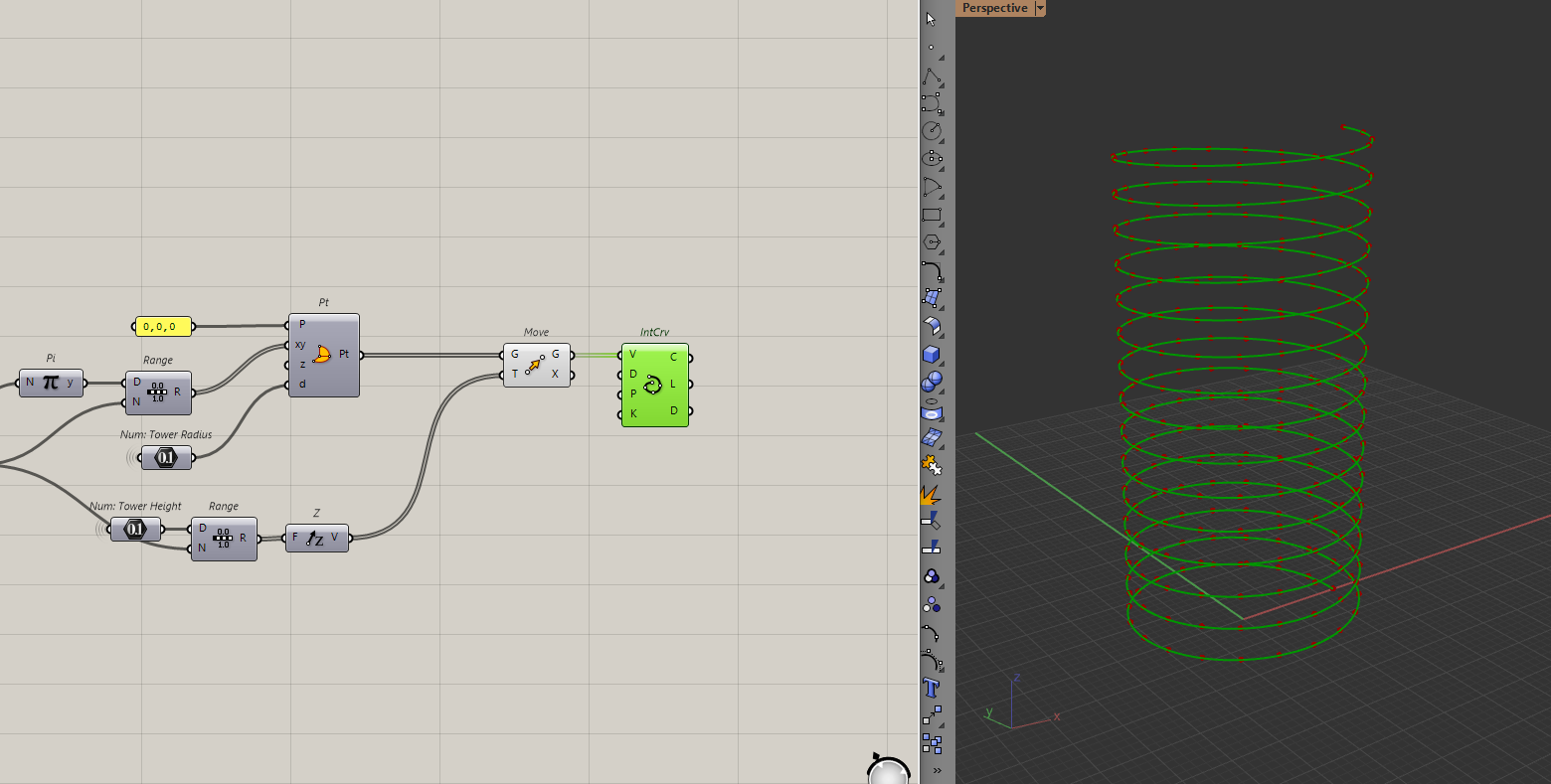
By connecting these points, I will get my helix.
This is where you can play around with the number of points and turns to see what it does to the helix and choose the helix you like best.
Even though I have the helix, I just need the points because I want to "pull" these points to the conical surface from earlier.
To ensure that these points fully envelop the tower, I will add some "fat" to the numbers I have used to create the points. I do this to account for any numerical errors that might come from having the points and surface in the same location.
It's hard to explain if you haven't done many geometric operations in Grasshopper before. But it's a precaution that I am taking now. To do that, I will just add some distance to the height and radius when I first created the points.
Remove excess points and pull those points to the surface
Because I have points that are above the tower, I need to cull them out before I pull them. To do that, I will delete points that have a higher elevation than my tower height.
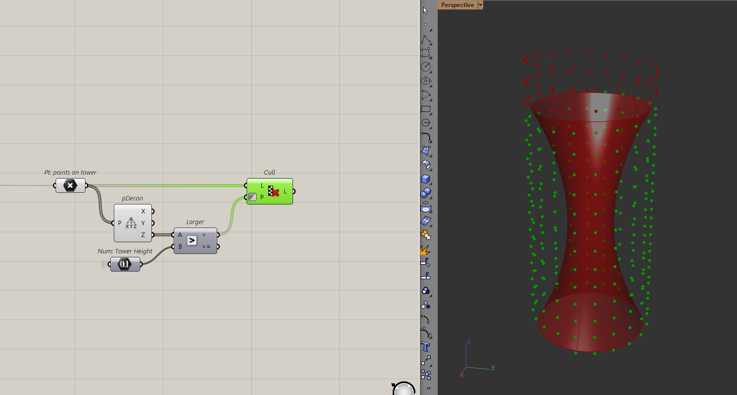
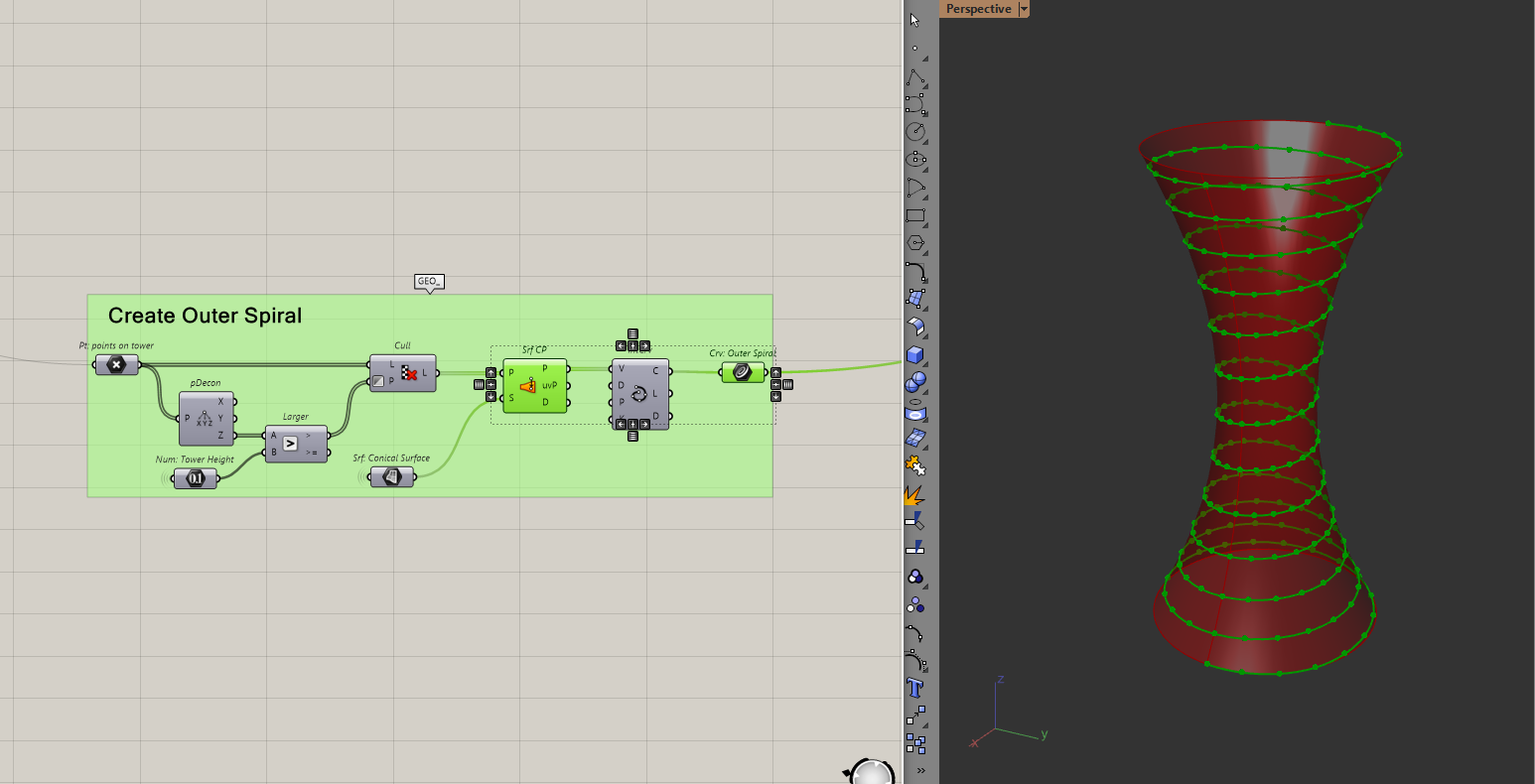
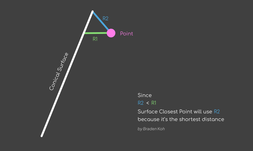
Then I will use the surface closest point component to "pull" my points to the surface. I can then interpolate these points to create the helix. This will be the outside of the ramp.
Note: In hindsight, I didn't have to add distance to the "height" when I created those points
Merging the Helix to the roof
With the helix defined, I can work on what I think is the most complicated part of the model. Which is merging this helix to the roof.
Before I do that, I need to make sure that the helix ends at the tower height. Because I used surface closest point, there is a chance that several points got pulled to the top of the surface.
Cleaning the Helix
I can check that by intersecting a plane at the tower height with the helix. If the helix is "clean" then I should only have one point (the end of the curve) but I have two points.
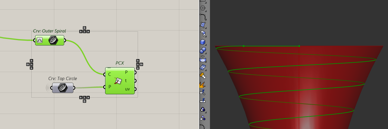
This is because of the way surface closest point behaves.
To clean this up, I will shatter the helix where it meets the roof.
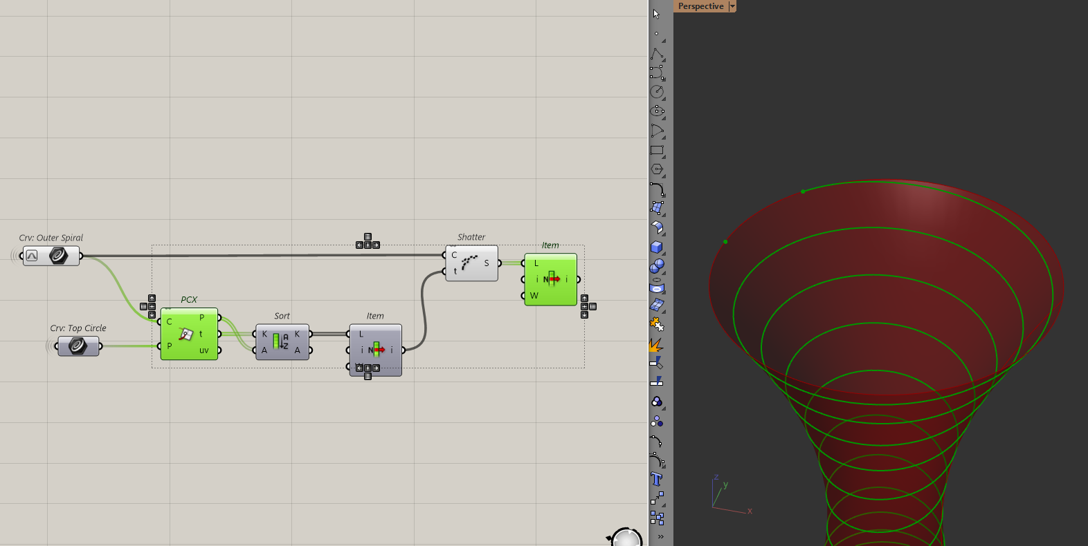
which gives us a clean helix.
Creating the inner spiral
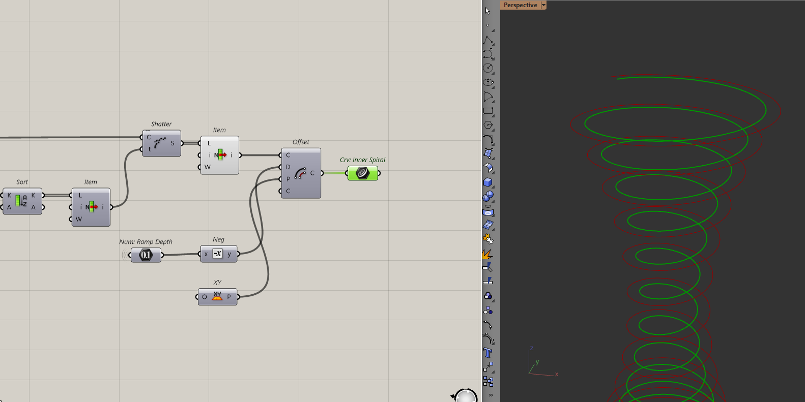
We can now make the inside of the ramp by simply offsetting the helix.
Later on, these two curves will help me create the ramp. But for now, let's keep moving on this transition.
Making the transition to the roof
With the two curves defined, let's look at how to merge this helix to the roof. Even though everything looks circular in this model, transitioning the spiral to the roof is not.
This is made obvious by seeing the model from a top-down view. As the ramp approaches the roof, you will notice that the curve doesn't create a circle.
Image Credit: EFFEKT completes spiralling Camp Adventure tower in Danish forest
This curve is actually made of two arcs, one that merges with the roof and another that comes back to complete the "circle". I'll call this the flat and transition arcs.
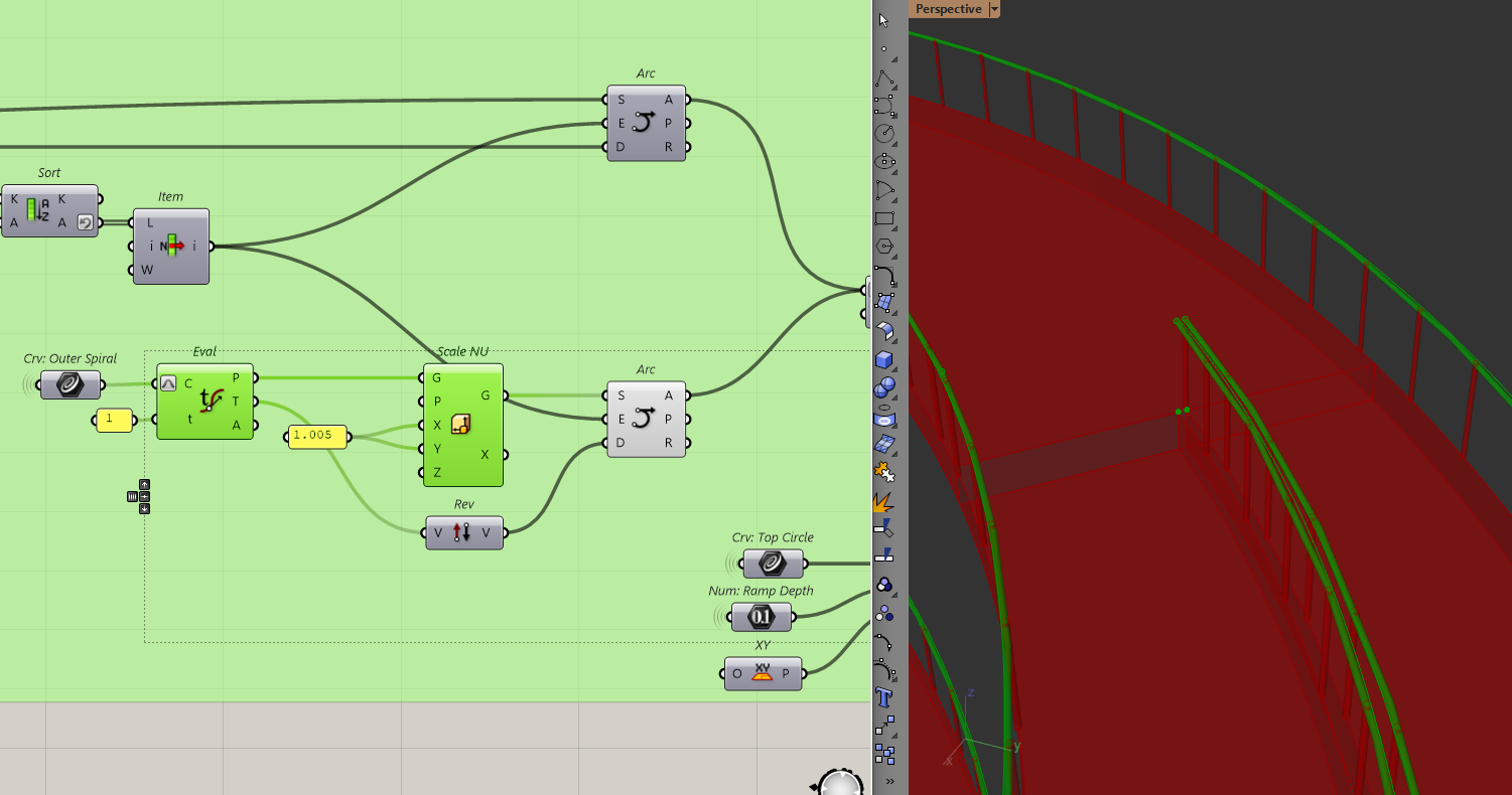
To create any of the arcs, I first need to find that point across the end of the helix (the green cross). I can do that by intersecting a line from the end of the helix to the top circle from before.
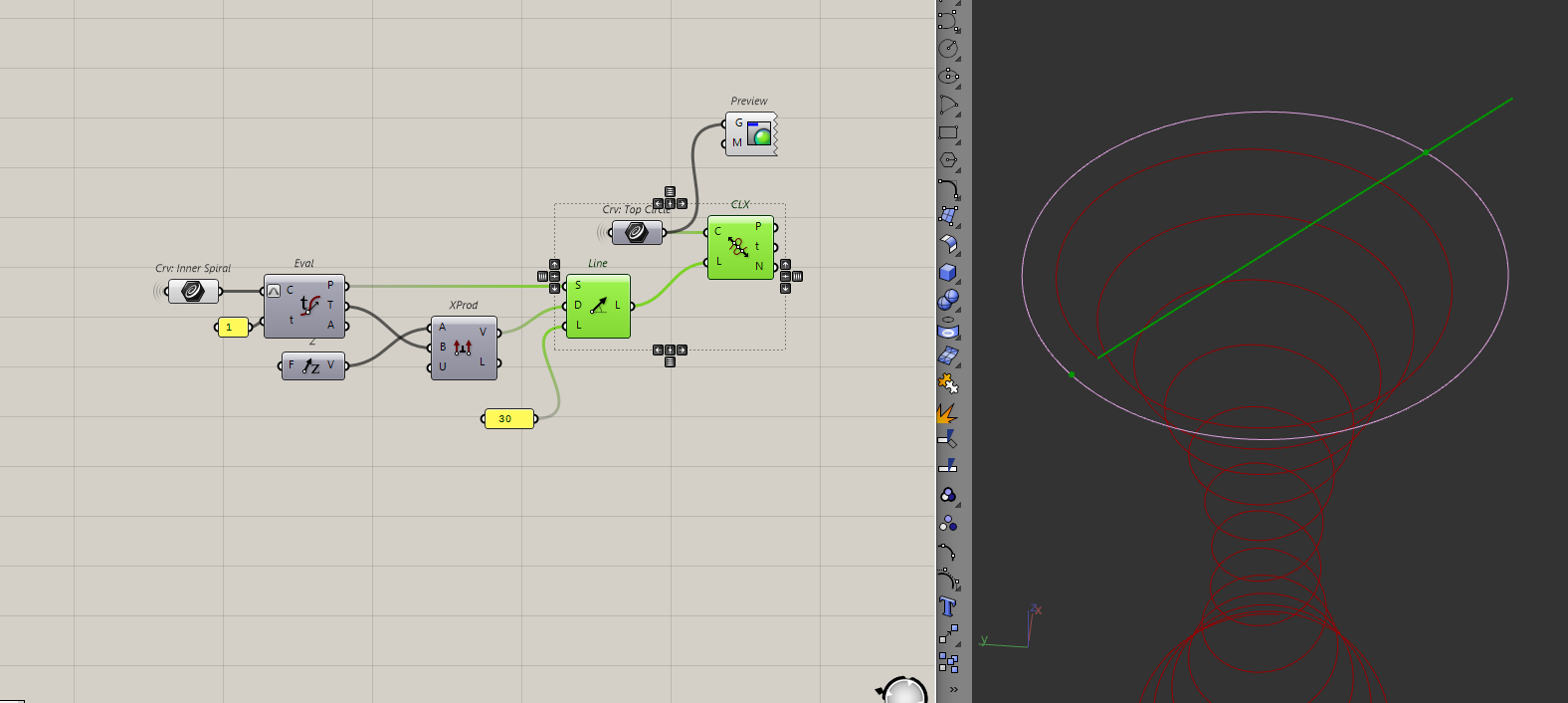
To create the line, I will first get the tangent of the endpoint of the helix. Then, I will do a cross-product between the tangent and the Z-axis to get the direction for the line. I will then use the line | curve intersection component to intersect the line with the circle.
In this case, the line length doesn't matter because the line | curve intersection component uses an infinite line. That's actually why I am getting two points.
Note: if cross-products are confusing/new to you, check out this link to get a better understanding.
Because we have two points, I'll choose the furthest one. I'll do that by sorting the points by their distance from the helix endpoint.
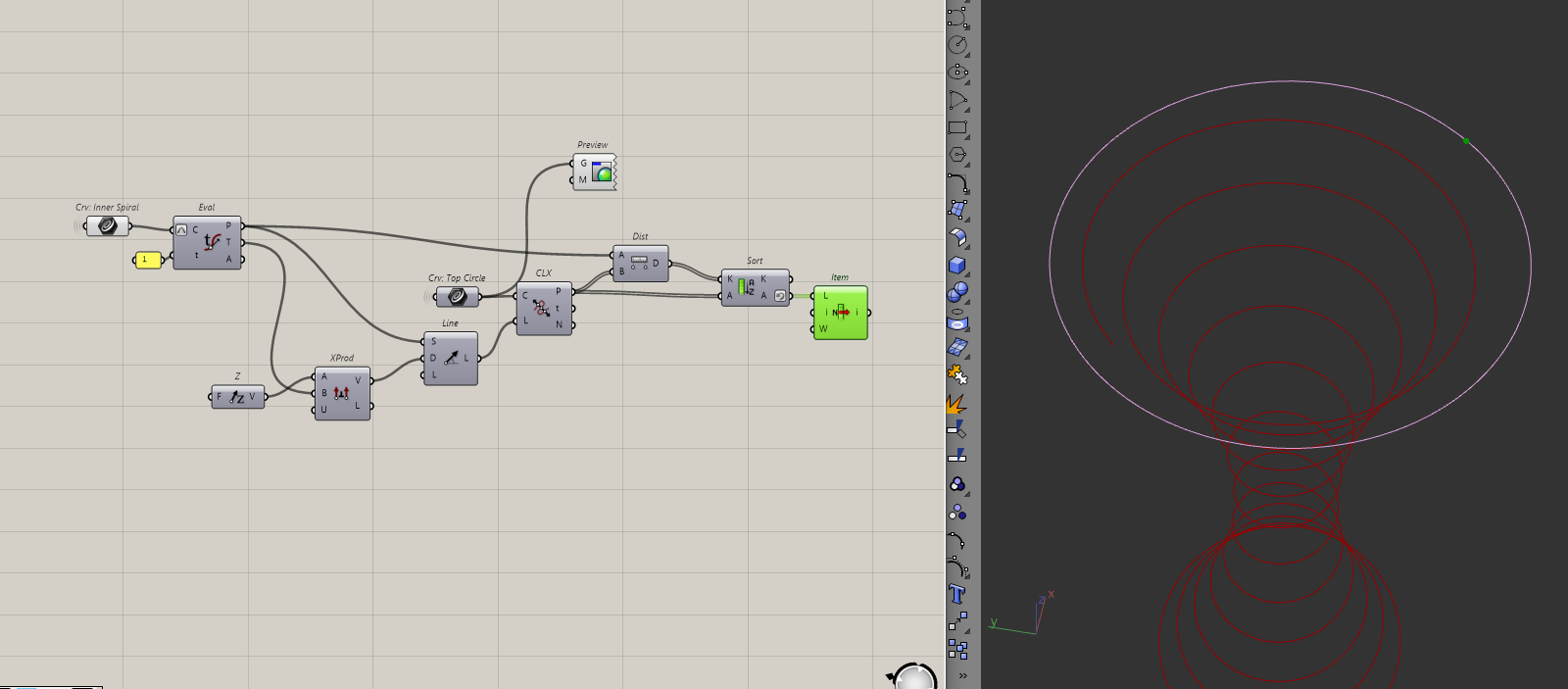
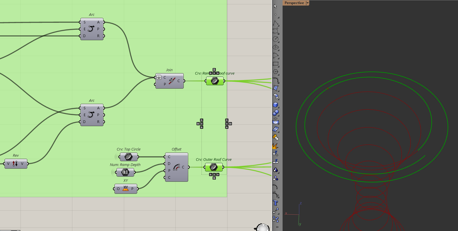
I will create the flat arc first, by using the endpoint of the helix, its tangent and the point that we've just found. I'll put those inputs into the SED Arc component to create the arc.
To create the transition arc, I will use the outer helix instead of the inner helix and repeat the same process.
All that's left is to join the curves. Since this curve is the inside of the roof ramp, I should also make the outside. It's simply the offset of the top circle from before.
Now that we have all our curves, we can start making the actual geometry for the model.
Making the ramp
Alright, let's backtrack to where I first made the outer helix. I will divide the outer and inner helix by some number, draw lines in between them, extrude those lines down and loft all of them to create the ramp.
Let's divide the helixes and draw lines between them.
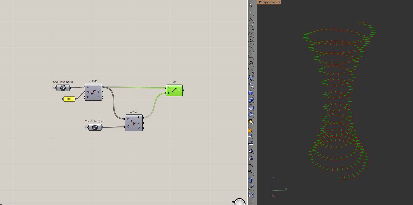
The number of points here doesn't matter as much, just pick a number that is large enough so you don't see any kinks in the ramp.
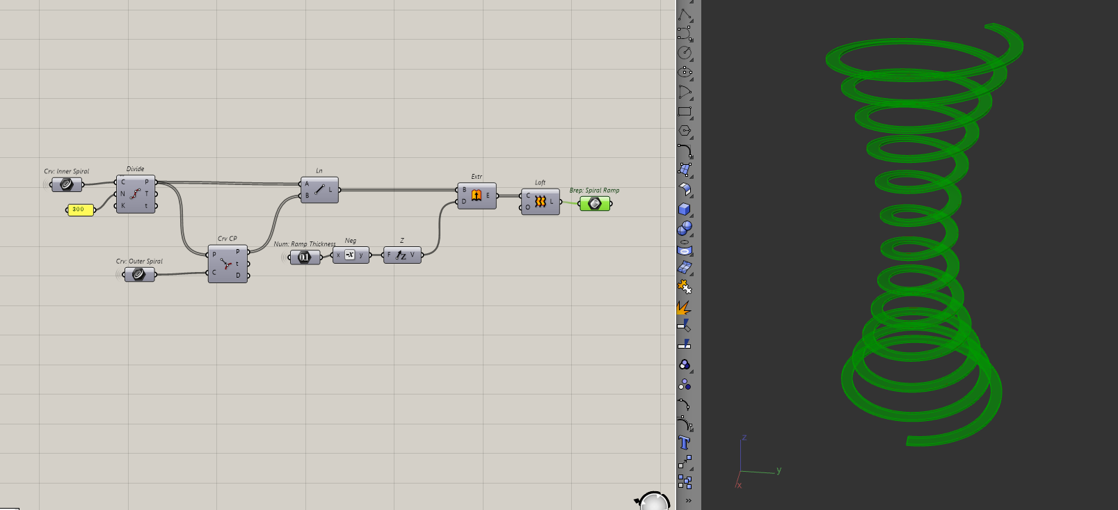
Then, I'll extrude the lines down and loft all of them.
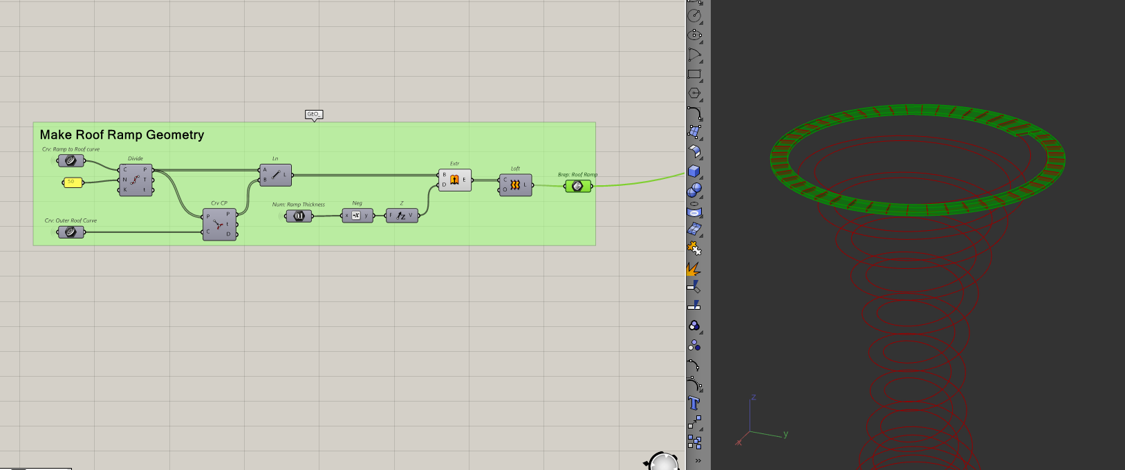
Making the roof ramp
By the same logic, I will make the roof ramp too. All I need is the inside and outside curves of the roof from before.
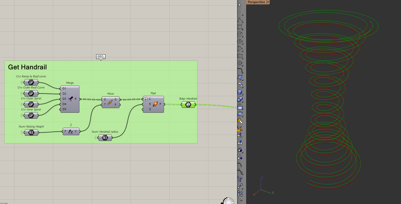
Creating the handrails
To do this, I will bring all the curves together then move them upwards and pipe them.
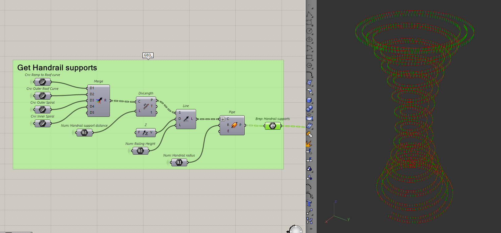
Then, to make the handrail supports, I need to divide the curves by some points and extrude some pipes to the handrail.
Everything looks good so far. But if you zoom into the transition of the ramp and the roof ramp, you will see that the handrails are clashing.
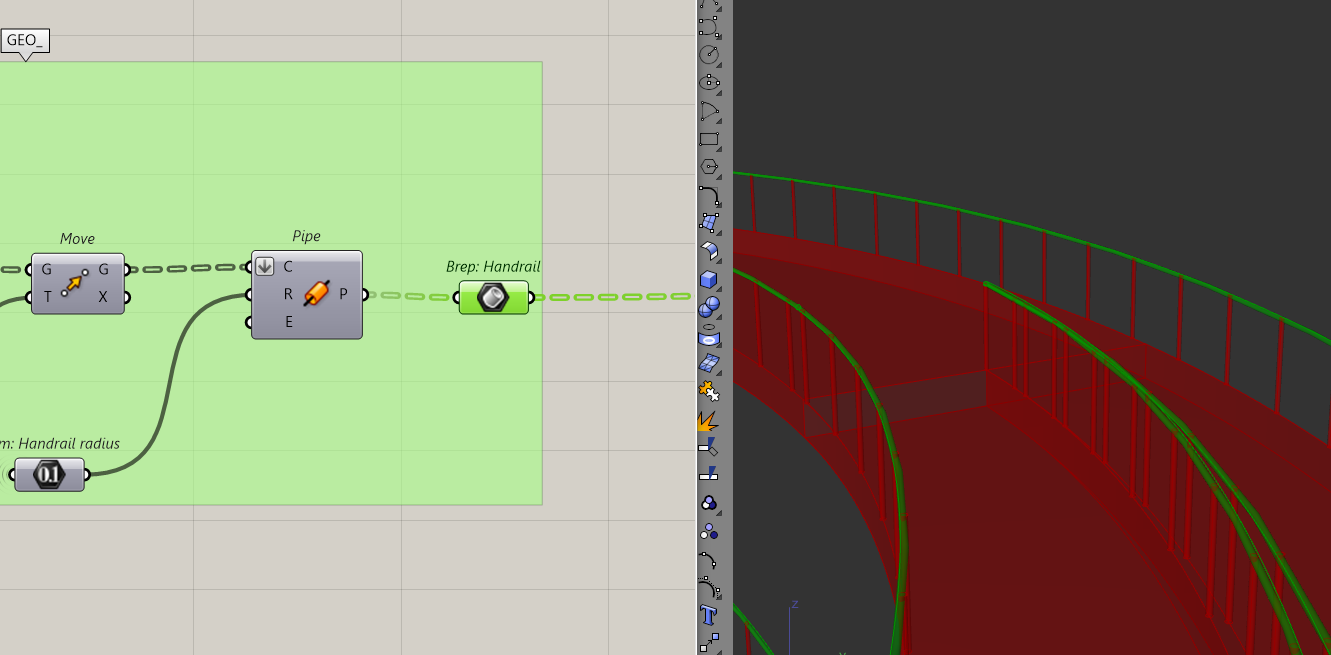
This is because we have two curves meeting at the same point. To solve this, I'll bring the transition arc inwards. I'll do that by slightly scaling down the outer helix end point I used to make that arc.
Creating the Diagrid
With all the internal geometry of the tower modelled, it's time to move on to the final piece, the Diagrid. Here is what the process will look like:
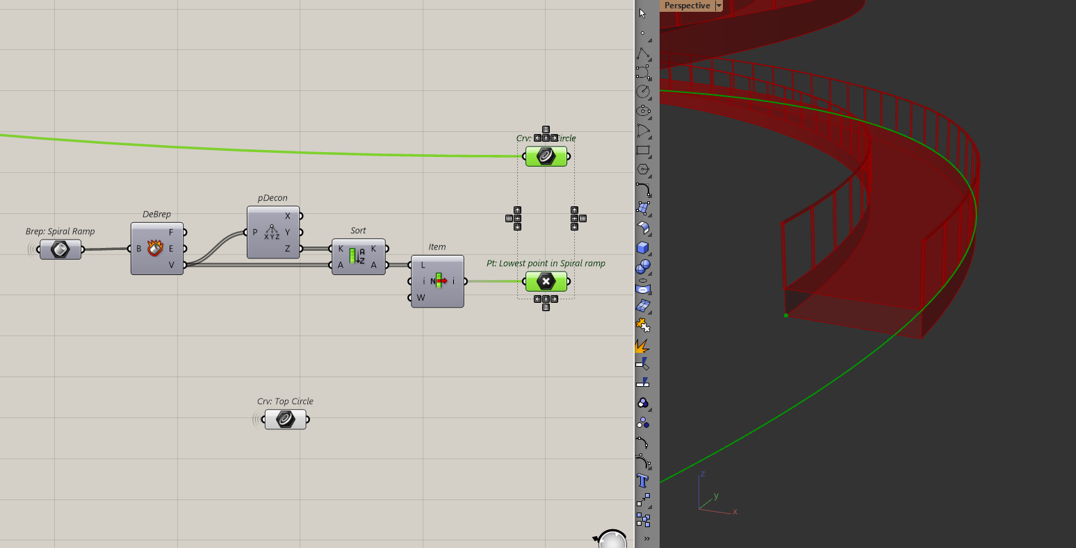
Let's go back to the start, where I created the two circles. Before I do anything, I need to make sure that the circles are still at the right elevation. When I created the ramp, I extruded the lines downwards, which means the bottom circle no longer lines up with the model.
To solve that, I will project that bottom circle to the same elevation as the lowest point of the model.
Now, I can start modelling the diagrid. I'll first divide both circles to get some points.
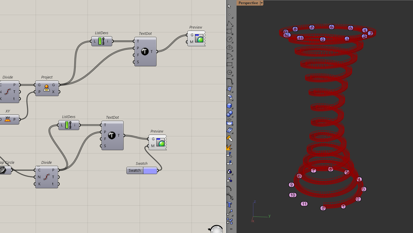
I am displaying the indices of the points to make their order clear because I am going to play around the order of how these points connect
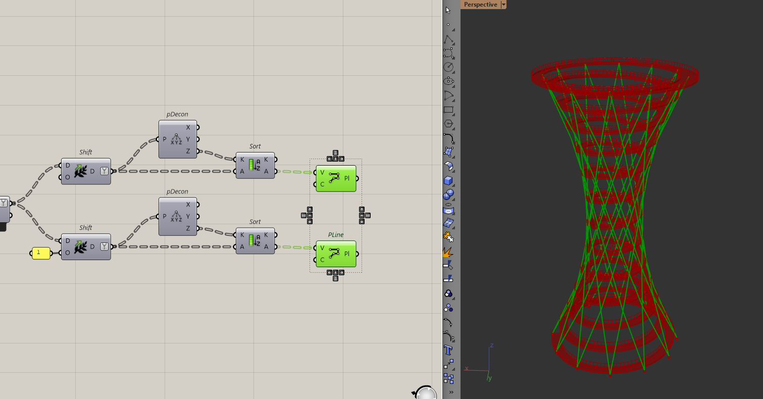
To create the diagrid, I want to connect the points of the bottom circle with every "nth" point of the top circle to create the "twisting" effect. I'll do this with the shift list component which shifts items in a list by a certain amount.
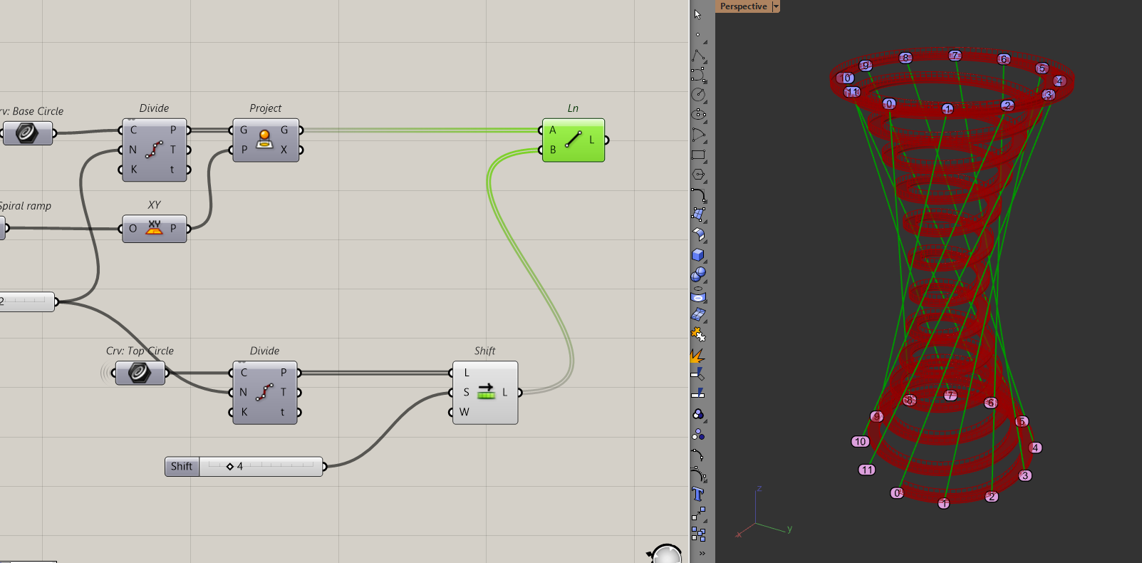
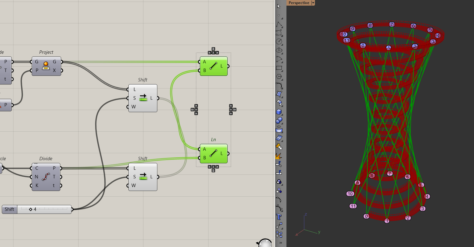
In this case, I am choosing 4 as my "n". That means every point on my bottom circle will connect to the 4th point of my top circle. To add the lines in the opposite direction, I just have to apply the shift list to the bottom circle too. As in, every point on the top circle should connect with the 4th point of the bottom circle.
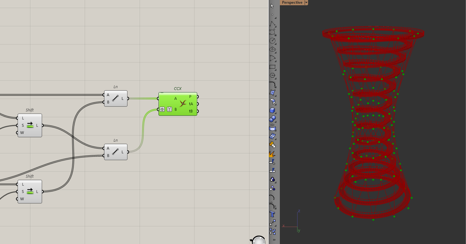
Now that I have the lines, they are still too far from the ramp. To bring these lines inwards, I will follow a similar approach to how I created the ramp. By "pulling" the lines to the conical surface.
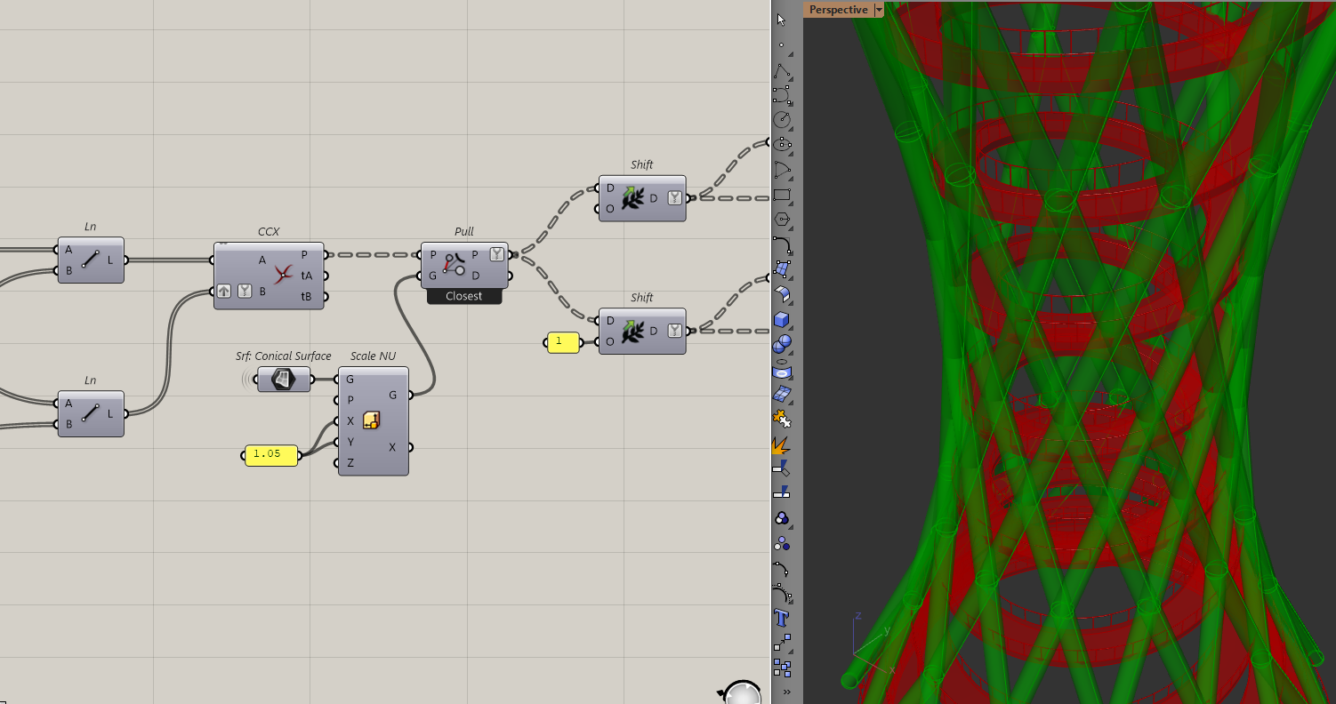
To do that, I want to work with points, so I will use the curve | curve intersection component to get all the diagrid points. Since I have two lists, one for the lines twisting to the right and another for the lines twisting to the left, I will have to just graph one of the lists and intersect both sides.
Now with all the points, I can pull them to the conical surface.
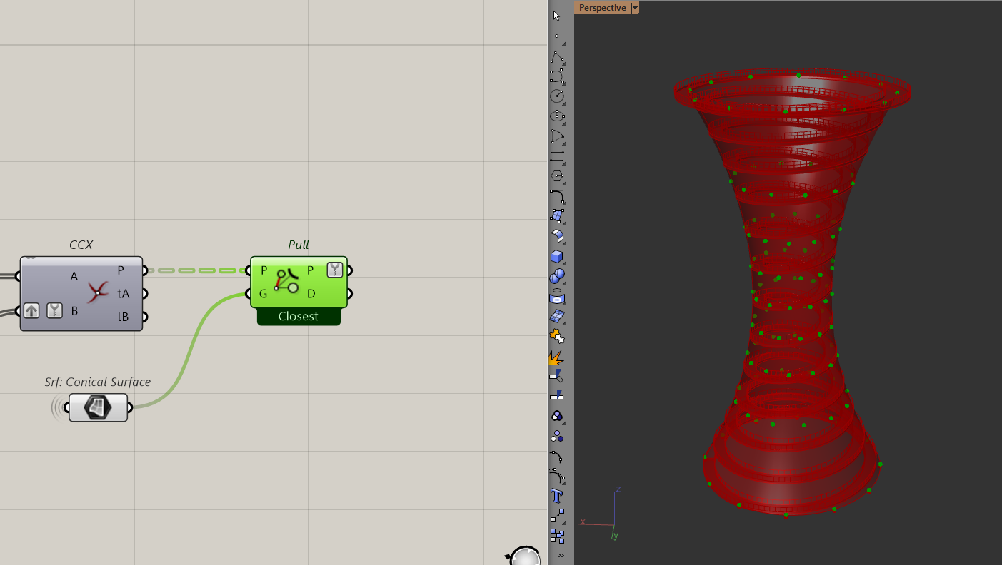
Then, to reconstruct the lines. Because of the way I intersected the lines before, all I have to do is to path shift the points forward and backward to reconstruct the lines.
Then I just need to pipe these lines to get the diagrid.
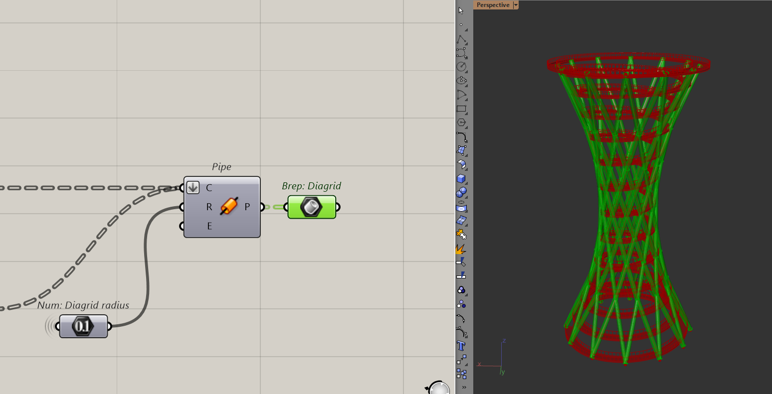
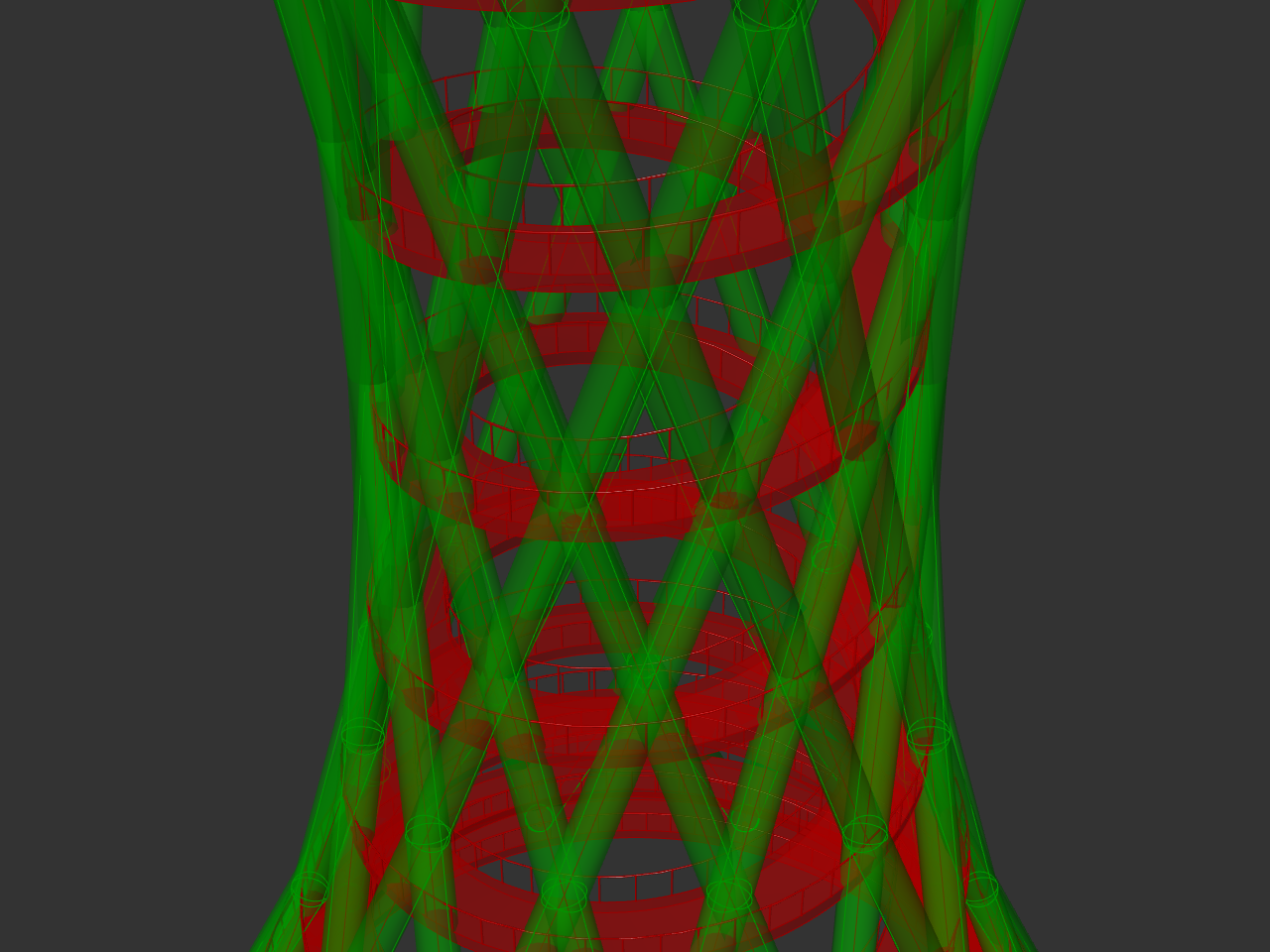
But if you zoom into the model, you'll notice that the diagrid is eating a lot into the ramp.
To solve that, I am going to scale the conical surface outwards by a factor. I am just doing this roughly to avoid clashing with the ramp too much.
Final Thoughts
And that's it! We've finished modelling this spiral tower. I can preview all the geometry now and even assign some colours to them.
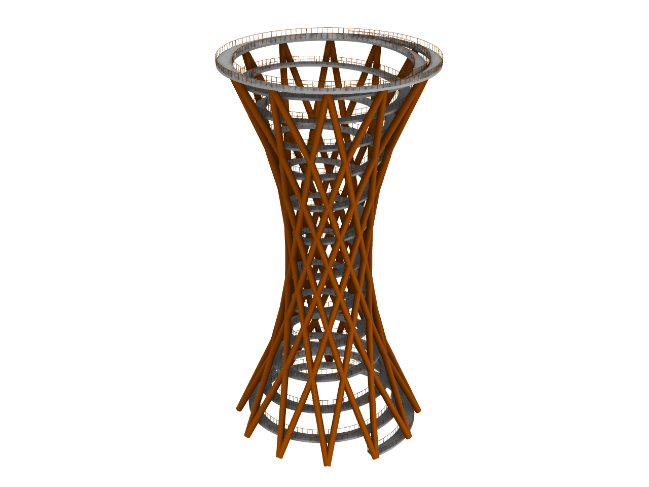
I enjoyed creating this model because there were a lot of "circular" geometry operations that I don't normally get to use.
I hope you've have found it useful and that this solution guide was helpful.
You can find the link to the full and cleaned script here: Spiral Observatory Tower.gh