
Winton Guest House Part 2
Solution Agenda
- Part 1: Modelling the Fireplace, Living Room and Bedroom
- Part 2: Modelling the Garage and Loft (this article)
- Part 3: Modelling the Second Bedroom
- Part 4: Cleaning up the script
This is part 2/4 of the Winton Guest House solution guide where we model the garage the loft of the Winton Guest House model. Just as a reminder, this is the anatomy of the model.
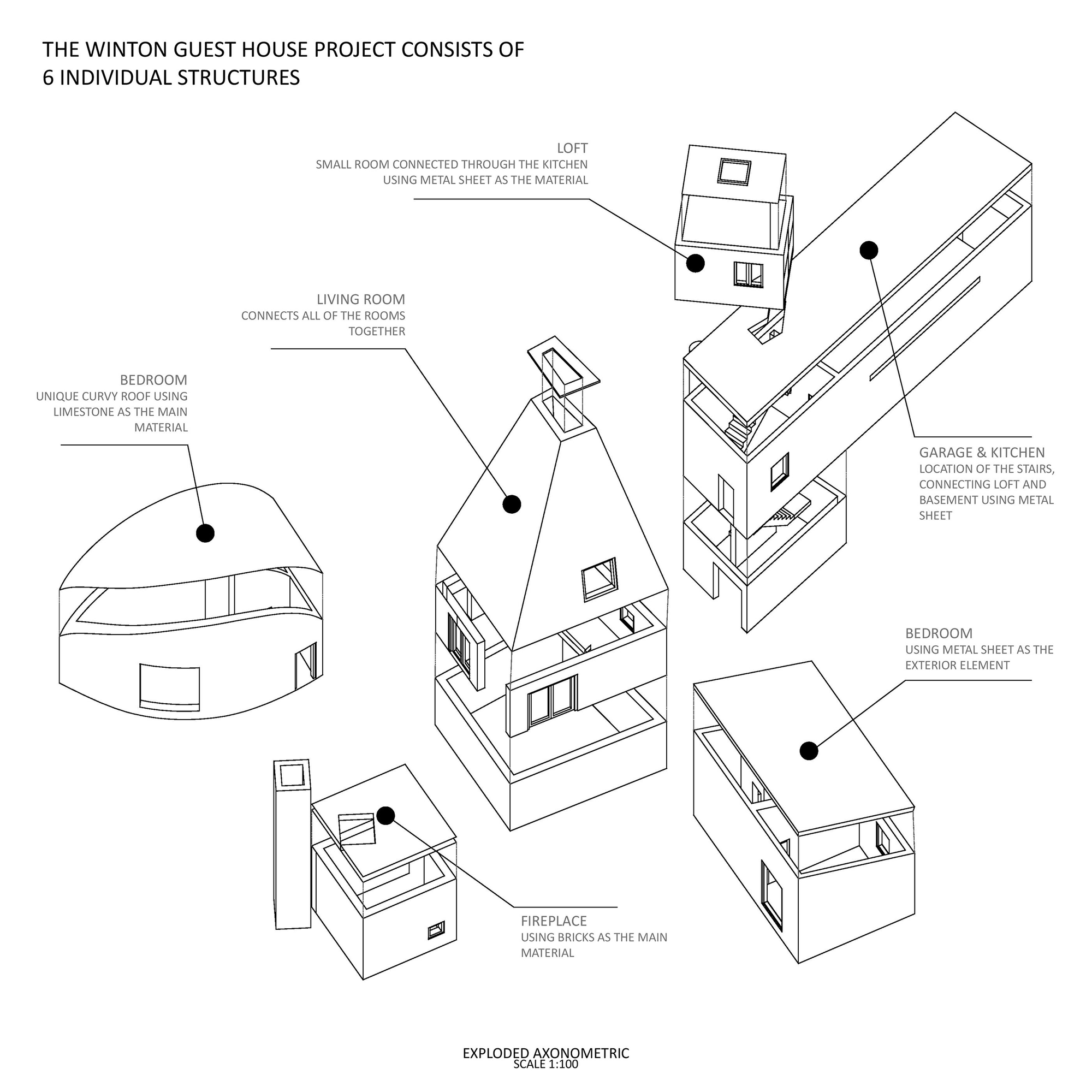
image credit: Behance
Let's get started
Creating the Garage & Kitchen
Like much of part 1, I start off by selecting a point on an edge of the Living room outline.

I am again, playing around with the curve parameter until I get a point that is close to the red cross in plan.

Once I have the point, I can start drawing the shape of the Garage. But to do that, I need to first find the right plane to draw the shape. That plane can be found by getting the face of the living room brep.
Much like how I have been selecting a point from outlines. I can also select a face from a brep. I do this via the deconstruct brep component.

To then get a plane from that face, I'll use the evaluate surface component. Similar to the evaluate curve component, this component also takes in a parameter. But instead of t parameter , it accepts a UV parameter . A UV parameter is like a t parameter but in two directions. Luckily, Grasshopper offers us a way to select a UV parameter visually using the MD Slider component.

Once I get the plane, I need to move it to the point, I found earlier. I'll use the plane origin component to do that.

From here, I can follow what I have done before and just create a rectangle in that plane I have found.

If this were the same scenario as part 1, I would have just extruded this shape, but this building is different. If you have a look at the plan view again, the ends of the building have a different orientation.
This is best represented by the two red lines in the plan view.

just to showcase what I mean, if I extruded the rectangle, I'll get a building that looks like this.

You can see that it's not right. So, to fix that I need to actually create another rectangle in the right orientation. In this case, it's aligned in the X direction

I then move the rectangle by some amount and then loft between the two shapes.

Note: I actually realized that the orientation for the building is wrong. You can just rotate the plane to get it close to what we see in the plan view
Creating the Loft
To create the Loft, I need to first create the column that supports the building. Since the Loft is tied to where the Garage is, I'll build the loft based on the Garage.
To create the column, I'll select a point from the Garage building that I have just created.

Again, I am playing with the parameter until I get this red cross.

From there, I can move the point a certain distance away from the edge, create a circle using the circle component and extrude it upwards to the height of the trailer building.

Then I can start creating the Loft building from the top of that column. To do that, I'll move the point of the circle to the top of the column. And then create and rotate an XY plane.

Using this plane, I'll create my rectangle but I need to include column too. To do that, I'll include the radius of the column when I create the rectangle. The diagram below better shows what I mean.

So, when I create the rectangle, I'll need to include the column's radius in the domain. I can do this by putting the dimensions of the rectangle and the column's radius in a list. I'll then pass this list into a bounds component to get a domain that includes the radius and the rectangle.

Then, I can just extrude the rectangle upwards by some amount to create the Loft

Final Thoughts
As you may tell, the process of modelling the buildings in part 2 were very similar to part 1 but with the emphasis on getting the orientation right.
In the next part, we look at modelling the final bedroom. See you there.
Get Part 2's script here
Link to Part 3: Modelling the Bedroom